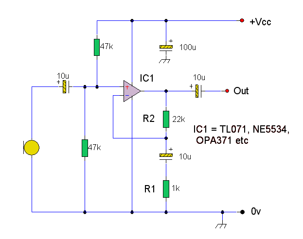
Notes:
Nothing too special here. The design is a standard non-inverting design, the input is applied to the non-inverting input of the op-amp which is pin 3 in most cases. The input impedance is 23.5k, the overall voltage gain is determined by R2 and R1according to the following formula:
Vo = ( R2 / R1) + 1
With the values of R2 and R1 on the diagram the voltage gain (for mid band, 1KHz) is approximately 23x or 27.2dB The gain bandwidth (bode) plot is shown below. This plot is simulated using the TL071 op-amplifier.

Operational amplifiers feature high gain bandwidth products, have a fast slewing rate and have extremely low noise. It is difficult to acheive the same performance using discrete components. Finally the overall signal to noise ratio has been calculated, the source was a 1k impedance microphone generating a 1mV pk-pk sine wave.

An impressive result of 110dB S/n at 1KHz is acheived. In practise this figure will be lower and determined by the quality of the microphone used
Circuit by
Source: zen's circuit directory
|


